top of page
Construction

Figure 27. Image of Drawing Tree

Figure 28. Image of Drivetrain sub-assembly mounted to rear chassis segment
In this image, many components were 3D printed from the motor cover and mount to the gears in the drivetrain. The two gears are spaced according to the center distance calculated and are being fastened using a setscrew. The motor mount and gearbox required the use of threaded inserts in order to fasten them together, a soldering iron was used to heat up the threaded inserts until they could melt the material and once cooled, they were stuck in place.

Figure 29. Image of Rear axle being machined in a lathe.
In this image, the rear axle can be seen machined on a lathe which is the only component that was going to be machined. This was the case since the team designed the RC so that the majority of the components could be manufactured in-house through additive manufacturing in the form of 3D printing. The rear axle was machined so that it is 6mm in diameter, 11" in length so it can be attached to the axle ends that were purchased for the wheels. A hole, 3mm in diameter will be drilled on either side of the axle so that a pin can be inserted to fasten the rear axle and the axle ends.

Figure 30. Image of Rear axle being sanded in a lathe
This image shows the rear axle being sanded down after being turned in a lathe. The rear axle was initially dimensioned to be just slightly larger than the ball bearings so that it would then be possible to use sandpaper to then further remove the material until the bearing could fit. This allowed for a really close tolerance as the shaft dimension was being checked quite often to make sure it wasnt being made to small and the bearings would be loose.

Figure 31. Image of slot being machined for the key in a vertical mill on the Rear axle
Here, the rear axle is now being machined in a vertical mill to create a slot where the key will be able to be slotted in so that the spur gear can be fastened to the shaft. This required careful measurements beforehand to ensure no errors were going to be made as this would then cause the project to be delayed waiting for another axle to be machined. To solve this problem, marks were made after carefully measuring the dimensions of the slot to ensure accuracy.
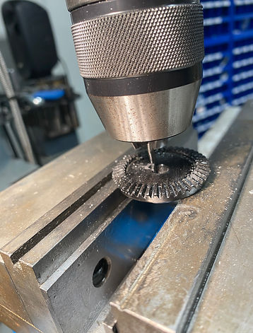
Figure 32. Image of key slot being machined on bevel gear
The purchased bevel gear can be seen machined in the image above in a vertical mill in order to create the slot for the square key to be fitted. Since there was only one bevel gear at hand, it was going to be important that no mistakes were made so no replacement would have to be purchased. To machine the slot, the gear was machined using a 1/8" end mill bit and small increments of .01mm of material was removed each pass. This allowed for the slot to be machined without any damage being done to the bevel gear.
Figure 33. Video of threaded inserts being inserted
This video here is demonstrating the basic process of how threaded inserts were utilized throughout the manufacturing. Here, a threaded insert is being heated up using a soldering iron and once it reaches the melting point of the material, it will start to dig in. This process was very similar to the other components that also used inserts like the mounts for both the motor and battery as well as the gearbox. The inserts allowed the use of metal fasteners since it would prevent the metallic fastener from causing fatigue in the PLA + that is being used until it eventually fails.
Figure 34. Video of rear axle being machined in a lathe
The rear axle can be seen being machined using a lathe out of aluminum. During the manufacturing one of the issues that arose was the axle not being concentric throughout which was caused by the absence of the tailstock as can be seen in the video, or rather not seen. Once the tail stock was put into place, this gave the aluminum shaft much more stability and it was possible to finish the manufacturing of the axle with no further issues.
Figure 35. Video of slot being machined on bevel gear
The bevel gear can be seen being machined using a vertical mill to machine out the slot for the square key. The gear was clamped down using the vice and with a very small end mill bit of 1/8" the slot was machined very slowly to ensure no mistakes would occur. As can be seen in the video, small increments were taken when removing material which allowed for the slot to be manufactured without any issues
For the remainder of the project, the manufacturing process has stayed the same with 3D printing being the main form of manufacturing. Most of the components in the project will be 3D printed with the exception of the bevel gears and the axle along with fasteners. That being said, there was a need to add inserts to the printed components so that the fasteners wouldn't dig in to the material since the RC was going to be taken apart multiple times, this will eat at the threads of the PLA + material and so a soldering iron was used to place threaded inserts into components that needed to be fastened to the chassis. Besides 3D printing, turning using a lathe and milling using a vertical mill were utilized. The vertical mill was used to create the slots in both the rear axle and the bevel gear. The lathe was utilized to machine the rear axle from an aluminum piece of stock. The use of the belt and disc sander was also utilized to create the square key by slowly removing material from a larger stock piece and then parting it off using the band saw. That being said, as previously stated the majority of the components manufactured were done using additive manufacturing using 3D printers.
bottom of page