
CWU Vieyra RC Baja
FALL:
WINTER:
SPRING:
Engineering Report:
INTRO
This is a project conducted by Roberto Vieyra in collaboration with lab partner Rogelio Arroyos. The engineering problem chosen was the participation in the RC Baja competition where the design of a functioning RC vehicle was the end goal. Rogelio will be responsible for the suspension and steering, while this portion of the project will be mainly on the drivetrain and chassis components. The main focus will be on the design of the chassis and drivetrain and also performing engineering analysis on the designs to create an RC that will be able to compete in two events. The Slalom-and-sprint and the Baja events will be a demonstration of the RC's maneuverability and performance. This website showcases the design, development, and testing of the RC Baja vehicle.


Results
Drop Test:

Figure 6. Deflection test results
The deflection test was performed to ensure the adhesive would not exceed the ultimate tensile strength of the material that was applied to join the two halves of the chassis (req.12) and the clerance would be enough to not hit the ground between the bottom of the chassis (req.14). During calculations the assumed load was 30lbf but what the actual load was about 22.05lbf as the maximum. Based on this information the stress was calculated to be 6.234psi and was well within the ultimate tensile strength. The deflection was fairly close to what was calculated but it is necessary to increase the clearance between the chassis and to ground as there were times where the chassis would hit the ground making the deflection 4cm.
Velocity Test:
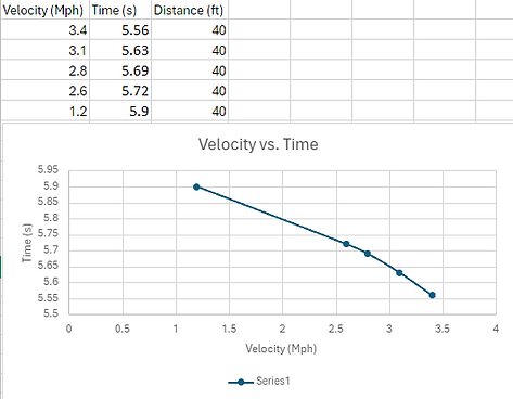
Figure 7.Velocity test results

Figure 8.Velocity test results with new 1980kV motor
The velocity test was important to determine the maximum velocity the RC can achieve (req.7). During analysis it was estimated a velocity of 30mph was expected, but during the actual testing, the actual maximum experienced was 3.4mph. The main issue was the 2400kv brushed motor that was being used, and was noticed to overheat quite easily just moving the RC at slow speeds. This was the case since the motor required more torque but was already receiving the maximum current possible causing the overheating issue. When the overheating began, the velocity started to drop which can bee seen in figure 7 where the best trial was the first and the slowest was the last as the motor was heating up. To mitigate this issue a new 1980kV brushless motor was used. There were no issues of the motor overheating and the maximum velocity was now closer to the 30mph at 13.2mph (see figure 8). Then based on the data tabulated it was possible to calculate an average acceleration based on the final velocity, distance traveled and the time it took to travel the distance. The acceleration calculated was 6.58ft/s^2 and so using this value the distance to reach a velocity of 30mph was calculated to be 147ft while the distance available during the test was 40ft and so it was not possible to achieve the absolute maximum velocity with the restrictions of the track used. This can easily be solved by taking the RC to a larger open area where it will travel the full distance.
Deflection Test:
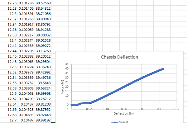
Figure 9.Instron Deflection results
The deflection test was performed to ensure that the chassis would be structurally sound, deflecting up to .1in (req.13) to withstand various drops and also to ensure that the adhesive used to join the two chassis sections would not fail during loading (req12). The maximum deflection that was experienced was about .104in while the calculated value was .0314in. The discrepancy here is due to the fact that during the analysis it was assumed the chassis would be solid rather than at a 25% infill. By multiplying the moment of inertia by the percent infill, this value was then used to recalculate the deflection. With the new moment of inertia, the deflection was now .126in and was much closer to the .104in with a percentage error of 16%. This error may be due to the fact that there are holes on the chassis that were not taken into consideration when the deflection as calculated.
The overall results of the project demonstrate that there are various losses that need to be taken into account when designing something like gears. It is also important to take into account the real world conditions of the component like with the chassis being assumed to be solid rather than at some infill. Because of this, some test predications had to be reanalyzed like with the drop test and deflection tests. After slight modifications to the equations, it was possible to get a predicted value closer to the test results. For example, instead of calculating the deflection as if it were a three-point load for the drop test, it was calculated by using the conservation of energy and setting it equal to the potential energy. With the three tests performed, this ensured the device had a chance at competing during the Baja competition which was one of the main goals. The results for the testing of the drop and velocity test could have been better since a speedometer on a phone was used which depended on your GPS location. This may cause some trials to be failed runs if the GPS is not accurate and with the drop test, a better camera could be used with a higher resolution to get a better reading of the values. Although the RC did not meet the 30mph requirement, the team was satisfied with getting the RC to go from 3.4mph to 13.2mph and allows the RC to have a better shot during competition. The acceleration calculated from the two different velocity tests saw an increase by about ten time and was .680ft/s^2 and 6.58ft/s^2 respectively. The deflection requirement of .1in maximum deflection was also not met since the deflection was about .104in but since it is just over the requirement, simply reprinting with a higher infill will suffice to meet the requirement. The drop test was half successful since the adhesive did not break, but there were times when the bottom of the chassis would hit the ground. To mitigate this, oil can be placed inside the springs which was not done before the testing and should increase the stiffness of the springs thus reducing the deflection as well as further increasing the clearance.