Schedule

Figure 44. Image of fall schedule

Figure 45. Fall schedule continued

Figure 46. Fall schedule continued
The main focus of the fall quarter is mainly to design and perform analysis on the chassis and suspension of the RC vehicle. During this process, many changes will be made to the designs but it is important to have a focus as to not deviate from the originals goal. For the chassis and drivetrain portion of the vehicle some major goals that were set as a design requirement were a maximum velocity of 30mph is achieved and the survival from a 2ft drop. Analysis was also performed to determine what size fasteners are sufficient enough to mount every component and not fail under load. In order to design for these requirements, the various components of the RC needed to be analyzed and so various analysis were performed to make sure that the RC would not fail during an impact at the maximum velocity or ensuring that the deflection caused from the drop is minimized. During the fall quarter it was also very important to document the parts that were being analyzed. In this project, most parts will be 3D printed and so many CAD drawing were created during the design and analysis.

Figure 47. Image of Winter Quarter

Figure 48. Image of Winter Quarter continued

Figure 49. Image of Spring Quarter
During the winter quarter, the main focus will be on purchasing, manufacturing and assembly of the project. One of the issues during this portion of the project is falling behind due to parts not being manufactured correctly or previously modeled parts not fitting together once printed. Most of the design and analysis will already have been done and at this point the design should already be finalized. If modifications need to be made, then that is something that must be documented and re-analyzed to determine if the issue was solved. There were quite a few modification made to some components like with the chassis. The chassis was to large for the print bed that was going to be used and so the chassis was split into two parts and then later joined with an adhesive. The gear box was also split into two pieces since the axle was not one diameter through its entire length. By splitting the gearbox, this allowed for the axle to be placed in the gear box and then essentially clamped down when the other half of the gearbox was fastened down. There was also a need to add some support to the axle close to where the knuckles of the wheel were and so the top half of the gearbox was modified to have a place where the axle could be supported. There were also issues with the axle during manufacturing due to user error but once these issues were fixed it was possible to assemble the device in time for the final presentation for the winter quarter.
The spring quarter similar to the winter quarter, will mostly involve the evaluation of the project and seeing if requirements were met. This will involve the testing of the RC vehicle in various ways some of which will determine the deflection caused by a drop an impact test at the maximum velocity to determine if the chassis will hold out. The major risk involved during this quarter is the permanent damage to parts and replacements will be required to be on hand otherwise the project will fall behind due to part malfunctions because of testing. Having performed the first test, as expected there were some 3D printed components that broke in the steering. The ball joints have a threaded insert but due to the force of the drop, this caused the insert to be pulled out of the plastic material for one of the ball joints. Thankfully because these sorts of issues were anticipated, a replacement was ready to be replaced which did not effect the budget since it was purchased ahead of time and this time they were made out aluminum. Increasing the clearance between the ground and chassis is also important since it was observed that the chassis was hitting the ground sometimes during testing, thus an increase of trials was required for better results. Then after performing the velocity test, it was observed that the current 2400kV brushed motor would not be enough since it was noticed to overheat often and needed more torque to get the RC moving from rest. Once the motor was switched to a 1980kV brushless motor, the issue of overheating was mitigated and it was possible to then perform another velocity test with the new motor (see figure 41, task 6c.i) . After testing again, the top speed increased from 3.4mph to 7mph. This may not seems like a lot, but the velocity depends on the distance traveled and the acceleration. Since the distance stayed the same during both testing's, this meant that the acceleration increased thus allowing the RC to achieve a higher top speed with the limited distance. The deflection test was another important test scheduled during this time period. Since the adhesive was applied to the center of the chassis, it was important that the adhesive would not fail when loaded at the same location. During this testing, there were no issues that caused delays and it was possible to load the chassis up to 40lbf with no issues.
Budgeting

Figure 50. Image of Part list of components purchased 55-000 and manufactured 20-000 as well as any fastners 50-000 used

Figure 52. Part list of components purchased (continued)
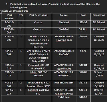

Figure 51. Part list of components purchased (continued)

Figure 53. Part list of components purchased (continued)

Figure 55. Image of total expenditure
Figure 54. Part list of components not used in the final assembly of the RC device
Fall Update:
The budget for this quarter will mainly include the expenditure of components for the RC like the axles and motor. These are essential to buying during the fall quarter as most analysis will involve the motor or axle dimensions and it is important to have that ready. Most of the components purchased were for the suspension portion of the RC like the servo, transmitter and the shocks with the receiver costing the most. For the chassis, the expenditure involved the purchase of the battery, motor, axles and the fasteners used to mount things to the chassis. The main portion that the budget will go to for the chassis and drivetrain is the 3D printing of components. Most of the components will be 3D printed for the chassis which will include the chassis base, mounts for the motor and battery respectively and also the gears for the drive train.
Winter Update:
During the winter quarter, the budgeting expense will involve mostly the manufacturing as this is the main aspect that will take place and most of the 3D print will occur during this time. This will also involve the purchase of more material as it could be possible that modeled components don't match with the purchased component like the motor not fitting in the motor mount and more expense will have to be made to correct it. Which can be seen in the increase of the purchased cost since new axle ends were purchased because the ones that were previously bought did not fit the knuckles. Other than the wheels and the hardware to mount the knuckles to them, there were no major changes to the budget. The wheel and knuckles alone were $72 and $86 (Figure 45) plus the addition of the battery charger at $62 with a total price of 220 for these components alone. Cheaper alternatives would be looked into for the wheels and knuckles. Another reason for the increase this quarter was due to the ESC burning up due since the rating of the ESC was close to what the motor was rated at and most likely slightly exceeded the amperage of the ESC drawing to much power and causing it to burn out. If someone were to build this product now, the total cost would be much less since there were components that were not used (Figure 46) worth $162.7 thus bringing the cost to $584.77. If cheaper alternatives can be found for the knuckles, wheels and battery charger, this would bring the cost to about the originally set budget of $500.
Spring Update:
The spring quarter will involve mostly the purchase of testing equipment like slow motion cameras for the impact testing and drop test and the purchase of sensors for determining stress. There have been no major changes to the budget since the winter quarter and the only expense will be replacing any component that broke. During the initial drop test, the ball joints had broken but because the team had already purchased these in advance, it did not effect the budget. After some more testing was performed, it was then necessary to purchase a new motor RCV-55-008 and a new ESC RCV-55-007 (See figure 47). This then brought the total cost of the project to $745.51 taking only the purchased components into account. Then adding up all of the unused components (see figure 46) and the cost was $162.7. If someone where to then make this RC, they would only purchase the used components and ignore the components in the unused table bringing the total to $637.89. No major malfunctions caused the team to purchase replacement components, and if something did break it was most likely something that can be 3D printed thus not increasing the total cost by much.